“About us” – GIOTTO Project Partners Interview

Subrata Mondal | Dublin City University

Postdoctoral Research Assistant
Short Bio & role in the GIOTTO Project
I am a skilled and independent biomechanical research engineer with a background in advanced computational biomechanics of hard and soft biological tissues, medical devices, tissue regeneration/injury, interaction between medical devices and host tissue rendering and Finite Element Analysis (FEA). I have completed my Ph.D. from IIT mandi in Design and biomechanics. Strong research professional with a master’s degree focused on Applied Mechanics from Motilal Nehru National Institute of Technology, India. B. Tech in Mechanical Engineering. My Ph.D. is in computational modelling of bone and orthopaedic medical devices. I developed advanced technical skills in the design and failure analysis of orthopaedic implants and bone tissue regeneration. I have worked as a Postdoctoral Research Assistant in the laboratories of Prof. Nicholas Dunne (DCU) and Dr. MacManus (DCU) on the European Commission Horizon 2020 GIOTTO project My role in this project was to create computational models (multiscale modelling) of three different medical devices for bone tissue regeneration, as well as their associated bones (femur, pelvis, vertebrae), and tissue regeneration potential.
What are the main tasks you carried out, and with which results?
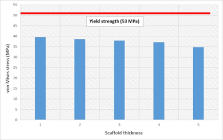
Fig. 1 Comparison of the peak von Mises stress distribution at the scaffold geometry as a function of thickness.
- Fluid-structure interaction simulation
I have developed a CFD and FSI model to investigate the shear stress and fluid flow under fluid perfusion and mechanical compression loading conditions. One-way FSI (i.e., the effect of fluid flow only) was performed to understand the effect of fluid perfusion through the scaffold surface. The von Mises stress, wall shear stress, and deformation due to the fluid perfusion have been determined. A CFD and FSI model investigated the WSS under fluid perfusion loading conditions. ANSYS FLUENT (ANSYS, Inc., USA) was used to develop the CFD model. A dynamic viscosity of 1.4 mPa.s was considered for the fluid domain. Ten noded tetrahedral elements were used for the discretisation of the scaffold. The edge length varies from 0.5-2 mm. The fluid volume was created by extracting the surface from the scaffold. In the CFD model, a constant velocity of 100 µm/s was applied at the inlet. At the same time, a zero-pressure condition was applied at the outlet. The scaffold surface was assumed as a non-slip wall boundary. The scaffold four side faces were considered symmetric boundaries. The CFD model was discretised with a polyhedral element.
The preliminary results of the FSI analysis showed a variation of WSS at the scaffold surface due to fluid flow. The resulting WSS imparted on scaffold surfaces in the case of fluid flow. The WSS was equally distributed in the scaffold architecture. More interestingly, it was found that a larger pore size could lead to a more equally distributed WSS. Almost 70% of total scaffold surface area experienced some level of fluid induced WSS, which was deemed adequate to stimulate bone differentiation. The observed von Mises and maximum shear stress distribution due to the fluid flow and applied displacement at the scaffold surface were well within the range.
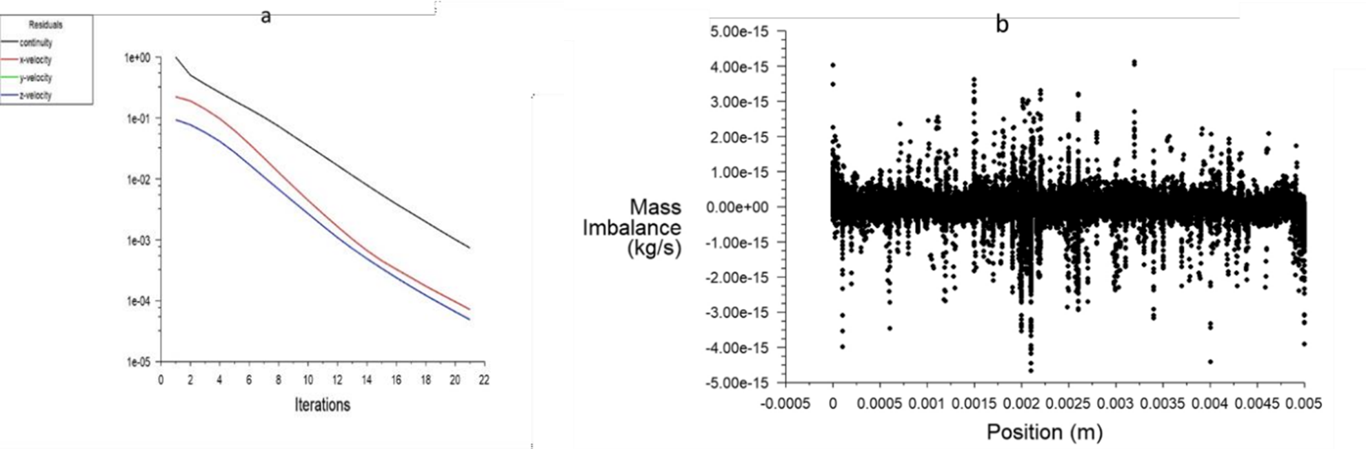
Fig. 2 Plots of the (a) residual or convergence and (b) mass imbalance of the CFD model
- Finite Element simulation of load transfer to Device 1
This task focused on designing multiscale modelling optimisation strategies that informed the final device design, also contributed to the choice of the surgical approach. This has been achieved by studying the load transfer, bone architecture, functional loading requirements, and surgical application constraints (e.g., mode of fixation for Device 1). A FE model of femur bone with plate fixation assembly, device 1 and femur stem has been developed. CT scan data (516×516 pixels, pixels size of 0.815 mm, and slice thickness of 1mm) was used to develop the 3D FE femur model. The fixation assembly is comprised of a plate, three bone screws (1-3), two cables (1-2) and two cable holders (1-2). The CAD model of the fixation plate, three bone screws, two cables, two cable holders, femur stem, and scaffold device were generated using SolidWorks (DS SolidWorks Corp., USA). The virtual positioning and operation were done in the femur bone with fixation plate assembly, femur stem, and the device in the Rhinoceros V 7.0 software (Robert McNeel & Associates, Seattle, WA, USA) software The FE model contained 121,426,8 elements (edge length varies from 0.2-3mm) as shown in Figure 3.
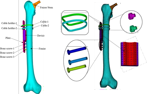
Fig. 3. FE model of femur bone with the plate assembly, stem, and device
The femur model was initially analysed with standing posture loading and boundary conditions (Figure 4). The femur model was subjected to the different bodyweight loading conditions:(1) 490 N, (2) 540 N, (3) 588 N, (4) 640 N, and (5) 860 N. The distal part of the femur bone was constrained with all degrees of freedom.
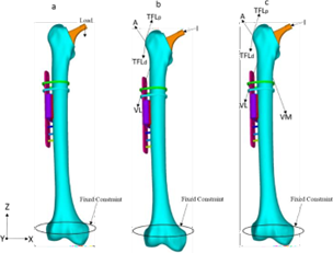
Fig. 4. Loading and boundary conditions at the FE model for (a) standing posture, (b) walking, and (c) stair climbing
As load transfer and strength are commonly expressed in terms of stress and strain, which are the critical parameters for the assessment of failure analysis. The equivalent stress and strain value were higher in the 860 N condition, and the corresponding results are presented in Figure 5. Although, the distribution pattern of equivalent stress and strain was almost similar for all the five load cases (1-5) in standing posture conditions.
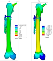
Fig. 5. Equivalent (a) stress, and (b) strain distribution at the FE model of femur bone with plate assembly and femur stem for the static loading condition of 860 N.
The bulk of the load was transferred through the plate fixation assembly as compared to the other components. The bone screws in the plate fixation assembly were the highest load-carrying components for both the contact conditions. The cable holders showed the lowest levels of stress distribution. The GIOTTO Device 1 was found to be within the safe limit (below the yield strength of PLLA/PCL/PHBV blend of 53 MPa) for all three physiological loading conditions.
- Bulk of the load was carried by plate fixation assembly compared to the GIOTTO Device In the plate fixation assembly, the bone screws were indicated as the highest load carrying component. Therefore, the present study concluded that the device would not be the main load-bearing component which well justified our hypothesis.
- Initial findings of load transfer through the fixation plate, GIOTTO Device 1, and bone are based on hip joint reaction force, muscle forces and physiological loading condition for realistic prediction of load transfer. The present study indicates that the stair climbing loading condition showed higher stress values at all the components than the standing and wolking.
Device 2
- FE development of Device 2
In this task, the FE model of the pelvic bone along with the electrospun scaffold design (grid and concentric design) of GIOTTO Device 2 was developed to predict the mechanical integrity, strength, and bone remodelling process. A CT data set was used for the development of the pelvic bone using MIMICS (Materialise, Leuven, Belgium) and CT scan data sets (stored in 512 x 512 pixels, pixel size of 0.803 mm and slice thickness of 1 mm) (Figure 6). Each bone was separated by cortical and cancellous bone using the manual thresholding method as mentioned in earlier studies to correct the partial volume effect problem. The cortical and cancellous bone were separated by using a threshold value of bone density 1.30 g/cm3, where density values more than the threshold value were considered as cortical bone. Based on the threshold value of bone density, 1.30 g/cm3 a threshold Hounsfield unit (HU) was determined, and this was found to be 2022 HU in our CT scan data sets.
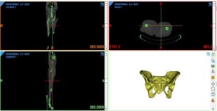
Fig. 6. 3D generation of the pelvic bone from CT data
The electrospun scaffold (design parameters, material properties, dimensions of the scaffold etc. provided by MERLN) was generated using Solidworks software (DS Solidworks Corp., Concord, MA, USA). The grid design of the electrospun scaffold was specified by MERLN. The GIOTTO Device 2 was manufactured from Polyactive (300 55/45). The device is comprised of a grid design: 2×2 cm, strand distance 2 mm, and thickness 100 mm. A virtual positioning was done in the fracture site of the pelvic bone with the electrospun scaffold.
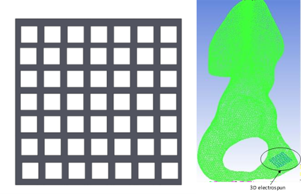
Fig. 7. Virtual positioning of the electrospun scaffold in the pelvic bone
The present FE model has been predicted the mechanical integrity, strength, and bone remodelling process due to the electrospun scaffold during bone healing.
Device 3
- FE development of Device 3
To study the effect of bone cement of GIOTTO Device 3 on the vertebral bodies and the adjacent components, a 3D FE model was developed. The FE model was considered helpful in biomechanical studies and understanding the recovery of the diseased vertebral body and the increase of the stress of the adjacent vertebral body. CT scan data was used to generate the 3D model of spinal geometry comprising of T11, T12, and L1. The image data were imported into the medical imaging software MIMICS 24.0. The vertebral geometry model was reconstructed from the scanned images and exported into the STL format. To correct the partial volume effect of the vertebral body, cortical and cancellous layers were separated. The cancellous and cortical layers were separated using the threshold value for bone density. Separation of cortical and cancellous bone was performed manually in MIMICS 24.0. Intervertebral disc and endplates were created as similar to previous literature. All the ligaments were created as linear spring elements. Each ligament was represented with ten parallel springs to distribute accurate load at ligament bone junctions.
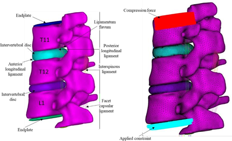
Fig. 8. FE model of the vertebra (T11-L1) with applied boundary and loading conditions
The fractured vertebral body caused the increment in the peak von Mises stress value at the T12 inferior endplate, L1 superior endplate, and T11/T12 intervertebral disc when compared with the healthy model. Whereas a decrease in the peak von Mises stress was observed at T12/L1 intervertebral disc. Compared to the fractured model, a decrease in the stress value was found at T12 inferior endplate, and L1 superior endplate after the injection of the bone cement at the T12 vertebra. At the same time, a bit of increment in the peak von Mises stress value at the T11/T12 and T12/L1 intervertebral discs was increased due to the injection of bone cement.
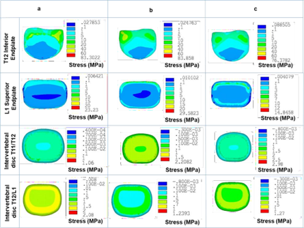
Fig. 9. The equivalent stress distribution at the intervertebral disc and endplates for (a) healthy model, (b) fractured model, and (c) fractured model with the injection of the bone cement
The von Mises stress in the vertebral endplate decreased after the injection of the bone cement, thus eliminating the risk of fracture in the adjacent vertebrae. Although, this study considered only one bone cement stiffness value for the analysis.
Has GIOTTO Project changed in some way your career or work?
I really enjoyed my time working on the GIOTTO Project. I had a very good experience working in a multidisciplinary project. I got to learn a lot. I had the opportunity to comprehend and investigate various scientific fields, which would be very helpful for my future research career. In this study, I ran the experiment on the mice brain for the first time, stepping outside of my computational comfort zone. This experience was very new for me and very rewarding. For the first time, I had the opportunity to work in multiple collaborations, which is excellent for my career. As an outcome from this project, one of my articles has been published and one is under-review. In addition to this, I also went to 2 prestigious international conferences while working on this project. Overall, the GIOTTO project has played a very important role in my career development and in my being an independent researcher.


Leave A Comment